
Page 314 - Ship Construction.DJ Eyres 6Ed
P. 314
Ch26-H8070.fm Page 303 Wednesday, October 18, 2006 7:01 AM
Pumping and Piping Arrangements 303
Closing
valve
Sluice
Mud valve
--- ใช้เพื่อการศึกษาเท่านั้น---
box
งานห้องสมุด ศูนย์ฝกพาณิชย์นาวี
Sea inlet box
Anode Sea inlet grids
positioned so that
bars are in fore
and aft direction
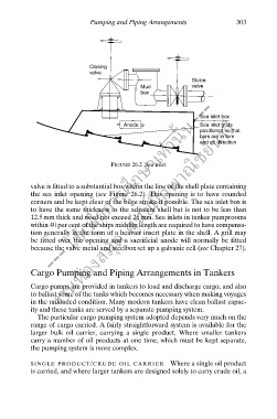
FIGURE 26.2 Sea inlet
valve is fitted to a substantial box within the line of the shell plate containing
ึ
the sea inlet opening (see Figure 26.2). This opening is to have rounded
corners and be kept clear of the bilge strake if possible. The sea inlet box is
to have the same thickness as the adjacent shell but is not to be less than
12.5 mm thick and need not exceed 25 mm. Sea inlets in tanker pumprooms
within 40 per cent of the ships midship length are required to have compensa-
tion generally in the form of a heavier insert plate in the shell. A grill may
be fitted over the opening and a sacrificial anode will normally be fitted
because the valve metal and steelbox set up a galvanic cell (see Chapter 27).
Cargo Pumping and Piping Arrangements in Tankers
Cargo pumps are provided in tankers to load and discharge cargo, and also
to ballast some of the tanks which becomes necessary when making voyages
in the unloaded condition. Many modern tankers have clean ballast capac-
ity and these tanks are served by a separate pumping system.
The particular cargo pumping system adopted depends very much on the
range of cargo carried. A fairly straightforward system is available for the
larger bulk oil carrier, carrying a single product. Where smaller tankers
carry a number of oil products at one time, which must be kept separate,
the pumping system is more complex.
SINGLE PRODUCT/CRUDE OIL CARRIER Where a single oil product
is carried, and where larger tankers are designed solely to carry crude oil, a