
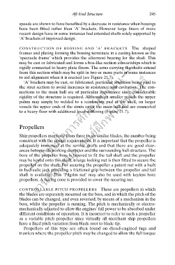
Page 256 - Ship Construction.DJ Eyres 6Ed
P. 256
Ch21-H8070.fm  Page 245  Wednesday, October 18, 2006  6:59 AM
                                           Aft End Structure                     245
                 speeds are shown to have benefited by a decrease in resistance when bossings
                 have  been  fitted  rather than ‘A’ brackets. However large liners of more
                 recent design have in some instances had extended shafts solely supported by
                 ‘A’ brackets of improved design.

                 CONSTRUCTION  OF  BOSSING  AND ‘ A’  BRACKETS          The shaped
                 frames and plating forming the bossing terminate in a casting known as the
                      --- ใช้เพื่อการศึกษาเท่านั้น---
                 ‘spectacle frame’ which provides the aftermost bearing for the shaft. This
                 may be cast or fabricated and forms a box-like section athwartships which is
                 rigidly connected to heavy plate floors. The arms carrying the shafts extend
                          งานห้องสมุด ศูนย์ฝกพาณิชย์นาวี
                 from this section which may be split in two or more parts in some instances
                 to aid alignment when it is erected (see Figure 21.7).
                   ‘A’ brackets may be cast, or fabricated, particular attention being paid to
                 the strut section to avoid increases in resistance and cavitation. The con-
                 nections to the main hull are of particular importance since considerable
                 rigidity of the structure is required. Although on smaller vessels the upper
                 palms may simply be welded to a reinforcing pad at the shell, on larger
                 vessels the upper ends of the struts enter the main hull and are connected
                 to a heavy floor with additional local stiffening (Figure 21.7).
                                                          ึ
                 Propellers

                 Ship propellers may have from three to six similar blades, the number being
                 consistent with the design requirements. It is important that the propeller is
                 adequately immersed at the service drafts and that there are good clear-
                 ances between its working diameter and the surrounding hull structure. The
                 bore of the propeller boss is tapered to fit the tail shaft and the propeller
                 may be keyed onto this shaft; a large locking nut is then fitted to secure the
                 propeller on the shaft. For securing the propeller a patent nut with a built
                 in hydraulic jack providing a frictional grip between the propeller and tail
                 shaft is available. This ‘Pilgrim nut’ may also be used with keyless bore
                 propellers. A fairing cone is provided to cover the securing nut.

                 CONTROLLABLE PITCH PROPELLERS These are propellers in which
                 the blades are separately mounted on the boss, and in which the pitch of the
                 blades can be changed, and even reversed, by means of a mechanism in the
                 boss, whilst the propeller is running. The pitch is mechanically or electro-
                 mechanically adjusted to allow the engines’ full power to be absorbed under
                 different conditions of operation. It is incorrect to refer to such a propeller
                 as a variable pitch propeller since virtually all merchant ship propellers
                 have a fixed pitch variation from blade root to blade tip.
                   Propellers of this type are often found on diesel-engined tugs and
                 trawlers where the propeller pitch may be changed to allow the full torque