
Page 194 - Ship Construction.DJ Eyres 6Ed
P. 194
Ch17-H8070.fm Page 183 Wednesday, October 18, 2006 6:57 AM
Shell Plating and Framing 183
performance whilst reducing any drag. Care is required in the design of the
bilge keel, for although it would not be considered as a critical strength
member of the hull structure, the region of its attachment is fairly highly
stressed owing to its distance from the neutral axis. Cracks have originated
in the bilge keel and propogated into the bilge plate causing failure of the
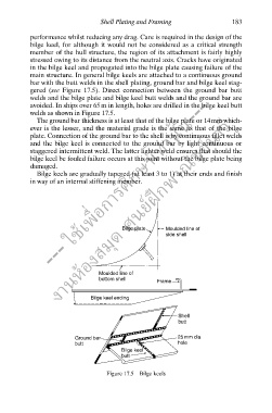
main structure. In general bilge keels are attached to a continuous ground
bar with the butt welds in the shell plating, ground bar and bilge keel stag-
--- ใช้เพื่อการศึกษาเท่านั้น---
gered (see Figure 17.5). Direct connection between the ground bar butt
welds and the bilge plate and bilge keel butt welds and the ground bar are
avoided. In ships over 65 m in length, holes are drilled in the bilge keel butt
งานห้องสมุด ศูนย์ฝกพาณิชย์นาวี
welds as shown in Figure 17.5.
The ground bar thickness is at least that of the bilge plate or 14mm which-
ever is the lesser, and the material grade is the same as that of the bilge
plate. Connection of the ground bar to the shell is by continuous fillet welds
and the bilge keel is connected to the ground bar by light continuous or
staggered intermittent weld. The latter lighter weld ensures that should the
bilge keel be fouled failure occurs at this joint without the bilge plate being
damaged.
Bilge keels are gradually tapered (at least 3 to 1) at their ends and finish
in way of an internal stiffening member.
ึ
Bilge plate Moulded line of
side shell
Moulded line of
bottom shell
Frame
Bilge keel ending
Shell
butt
Ground bar 25 mm dia
butt hole
Bilge keel
butt
Figure 17.5 Bilge keels