
Page 161 - Ship Construction.DJ Eyres 6Ed
P. 161
Ch15-H8070.fm Page 150 Wednesday, October 18, 2006 6:56 AM
150 Ship Construction
Generally two ground ways are fitted, the distance between the ways
being about one-third the beam of the ship. It is often desirable that the
cradle should be fitted in way of longitudinal structural members, and the
ground ways over slipway piling, these considerations deciding the exact
spacing. Some large ships have been launched on as many as four ways, and
in the Netherlands it appears to be common practice to launch vessels on a
single centre line ground way. The width of the ways should be such that the
--- ใช้เพื่อการศึกษาเท่านั้น---
launching weight of the ship does not produce pressures exceeding about
20 tonnes per square metre.
Ground ways are laid on supporting blocks and extend down to the low
งานห้องสมุด ศูนย์ฝกพาณิชย์นาวี
water mark so that they are covered by at least one metre of water at high
tide. To guide the sliding ways as they move over the ground ways a ribband
may be fitted to the outer edge of the ground ways. This could be fitted to
the inner edge of the sliding ways, but when fitted to the ground ways has
the advantage that it aids retention of the lubricating grease. Finally the
ground ways are shored transversely to prevent sideways movement and
longitudinally to prevent them from moving down with the ship.
The sliding ways covering about 80 per cent of the length of the vessel
form the lower part of the cradle, the upper part consisting of packing,
wedges, and baulks of timber with some packing fitted neatly to the line of
ึ
the hull in way of the framing. In very fine lined vessels the forward end of
the cradle referred to as the forward poppet will require to be relatively
high, and may be built up of vertical timber props tied together by stringers
or ribbands. This forward poppet will experience a maximum load which
may be as much as 20 to 25 per cent of the ship’s weight when the stern lifts.
It is therefore designed to carry a load of this magnitude; but there is a
danger in the fine lined vessel of the forward poppets being forced outwards by
the downward force, i.e. the bow might break through the poppets. To prevent
this, cross ties or spreaders may be passed below the forefoot of the vessel
and brackets may be temporarily fastened to the shell plating at the heads
of the poppets. In addition saddle plates taken under the forefoot of the
ship with packing between them and the shell may be fitted to transmit the
load to the fore poppets and hence ground ways.
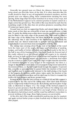
In many modern ships the bow sections are relatively full and little support is
required above the fore end of the sliding ways. Here short plate brackets
may be temporarily welded between the shell plating and heavy plate wedge
rider as illustrated in Figure 15.2. The design of the forward poppets is
based on greater pressures than the lubricant between the sliding ways and
ground ways could withstand if applied for any length of time. However as
the duration of pivoting is small, and the vessel has sufficient momentum to
prevent sticking at this stage, these high pressures are permissible.
At the after end of the cradle considerable packing may also be required,
and again vertical timber props or plate brackets may be fitted to form the
after poppet.