
Page 133 - Ship Construction.DJ Eyres 6Ed
P. 133
Ch12-H8070.fm Page 122 Wednesday, October 18, 2006 6:55 AM
122 Ship Construction
and production facilities can be called up so that the draughtsman can
ensure that the structural design uses the shipyards resources efficiently and
follows established and cost effective practices. Weld lengths and types,
steel weights and detailed parts lists can be processed from the information on
the drawing and passed to the production control systems. A 3-dimensional
steel assembly can be rotated by the draughtsman on screen to assess the
best orientation for maximum downhand welding.
--- ใช้เพื่อการศึกษาเท่านั้น---
The use of 3-dimensional drawings is particularly valuable in the area of
outfit drawings where items like pipework and ventilation/air-conditioning
trunking can be ‘sighted’ in the 3-dimensional mode and more accurately
งานห้องสมุด ศูนย์ฝกพาณิชย์นาวี
measured before being created in the 2-dimensional drawing.
Stored information can be accessed so that lofting functions such as pre-
paring information for bending frames and longitudinals, developing shell
plates, and providing shell frame sets and rolling lines or heat line bending
information for plates can be done via the interactive visual display unit.
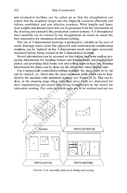
For a numerically controlled profiling machine the piece parts to be cut
can be ‘nested’, i.e. fitted into the most economic plate which can be han-
dled by the machine with minimum wastage (see Figure 12.4). This can be
done at the drawing stage when individual piece parts are abstracted for
steel requisitioning and stored later being brought back to the screen for
ึ
interactive nesting. The order in which parts are to be marked and cut can
3
DESIGN PARTS DEFINITION
2 3
1 4
4 3
1
2 3
4
PARTS LISTING PARTS NESTING
FIGURE 12.4 Assembly plate parts listing and nesting